
“Delco Remy” remains a registered trademark of General Motors Corporation, however, the ignition switch for the Stinson is considered obsolete by them. The Delco Remy part number for the switch is 1994524. You can find them on E-Bay occasionally.
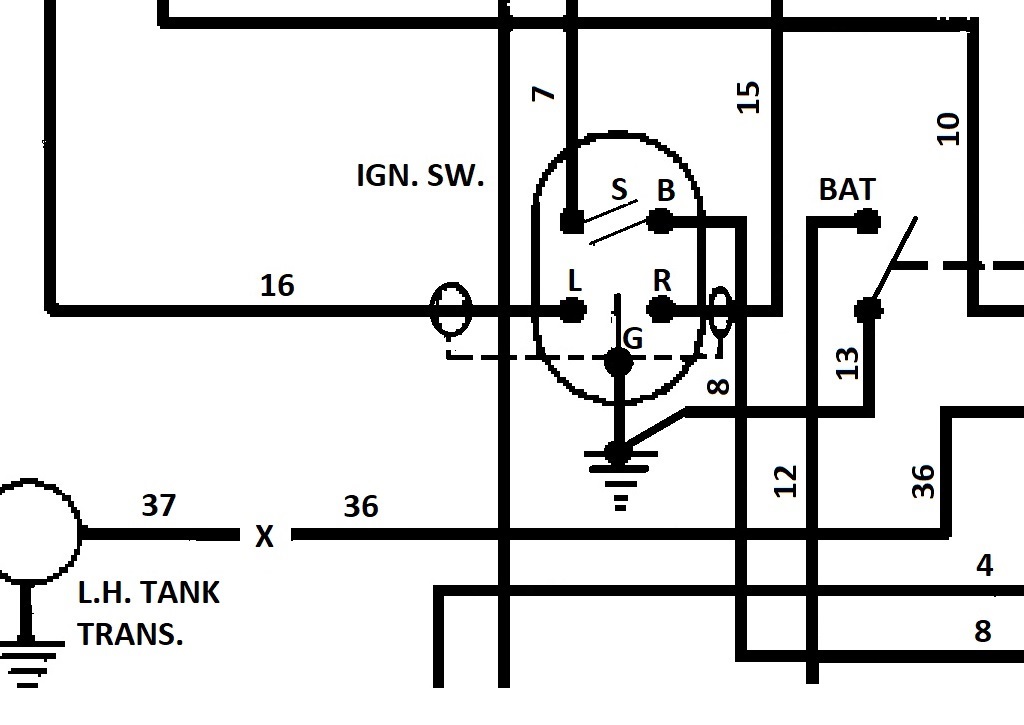
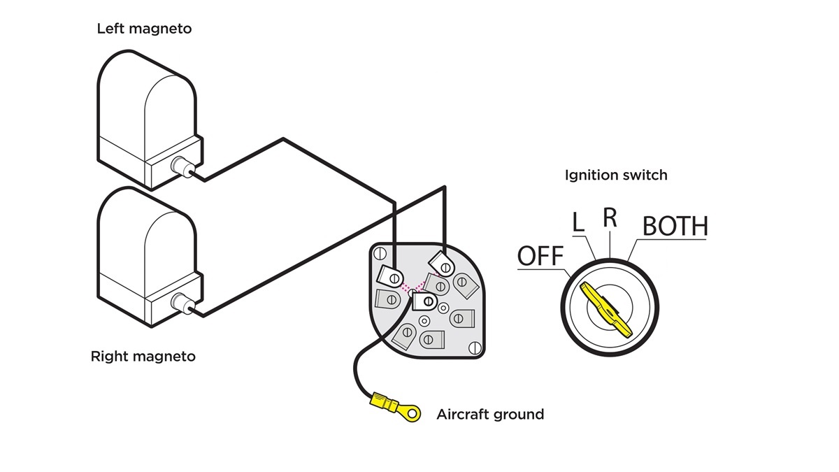
The “P” in P-lead originates from the primary winding within the magneto’s coil. To disable the magneto, the primary winding is connected to ground. The ignition switch controls the opening and closing of the P-lead circuits to aircraft ground. Within the internal mechanism of the Off/L/R/BOTH ignition switch lie the necessary connections. When set to OFF, both the left and right P-leads are connected to ground, deactivating both magnetos. In the L position, the right P-lead is connected to ground, while in the R position, the left is connected to ground. Selecting BOTH opens both P-lead circuits, activating both magnetos. Without P-leads, both magnetos would remain energized continuously.
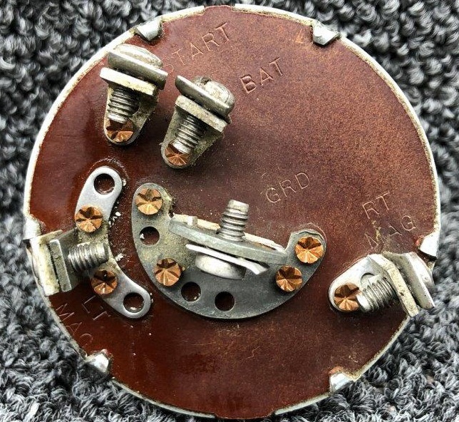
For Fritz’s Stinson 108-2, the following wire numbers coincide with the connections on the back of the ignition switch
| Ignition Switch Connection | Wire Number |
| GRD | AIRCRAFT GROUND, P-Lead shield wires |
| START | 7 (Starter switch to starter solenoid) |
| BAT | 8 (Starter switch battery terminal to power bus) |
| LT MAG (P Lead) | 16 (Starter switch P-lead to left mag) |
| RT MAG (P Lead) | 15 (Starter switch P-lead to right mag) |
OFF
LEFT
RIGHT

BOTH

Troubleshooting the Switch
Using an ohm meter, jumper between the pins on the back of the switch with no wires attached. You will either get an open or a short, depending on the switch position. See the chart BELOW for correct results.
| SWITCH POSITION | CONTACT | CONTACT | RESULT |
| OFF | GND | BAT | OPEN |
| OFF | GND | START | OPEN |
| OFF | GND | LEFT MAG | CLOSED |
| OFF | GND | RIGHR MAG | CLOSED |
| OFF | BAT | GND | OPEN |
| OFF | BAT | START | OPEN |
| OFF | BAT | LEFT MAG | OPEN |
| OFF | BAT | RIGHT MAG | OPEN |
| OFF | LEFT MAG | START | OPEN |
| OFF | LEFT MAG | RIGHT MAG | OPEN |
| OFF | RIGHT MAG | START | OPEN |
| SWITCH POSITION | CONTACT | CONTACT | RESULT |
| LEFT MAG | GND | BAT | OPEN |
| LEFT MAG | GND | START | OPEN |
| LEFT MAG | GND | LEFT MAG | OPEN |
| LEFT MAG | GND | RIGHT MAG | CLOSED |
| LEFT MAG | BAT | GND | OPEN |
| LEFT MAG | BAT | START | OPEN |
| LEFT MAG | BAT | LEFT MAG | OPEN |
| LEFT MAG | BAT | RIGHT MAG | OPEN |
| LEFT MAG | LEFT MAG | START | OPEN |
| LEFT MAG | LEFT MAG | RIGHT MAG | OPEN |
| LEFT MAG | RIGHT MAG | START | OPEN |
| SWITCH POSITION | CONTACT | CONTACT | RESULT |
| RIGHT MAG | GND | BATA | OPEN |
| RIGHT MAG | GND | START | OPEN |
| RIGHT MAG | GND | LEFT MAG | CLOSED |
| RIGHT MAG | GND | RIGHT MAG | OPEN |
| RIGHT MAG | BAT | GND | OPEN |
| RIGHT MAG | BAT | START | OPEN |
| RIGHT MAG | BATA | LEFT MAG | OPEN |
| RIGHT MAG | BAT | RIGHT MAG | OPEN |
| RIGHT MAG | LEFT MAG | START | OPEN |
| RIGHT MAG | LEFT MAG | RIGHT MAG | OPEN |
| RIGHT MAG | RIGHT MAG | START | OPEN |
| SWITCH POSITION | CONTACT | CONTACT | RESULT |
| BOTH | GND | BAT | OPEN |
| BOTH | GND | START | OPEN |
| BOTH | GND | LEFT MAG | OPEN |
| BOTH | GND | RIGHT MAG | OPEN |
| BOTH | BAT | GND | OPEN |
| BOTH | BAT | START | OPEN |
| BOTH | BAT | LEFT MAG | OPEM |
| BOTH | BAT | RIGHT MAG | OPEN |
| BOTH | LEFT MAG | START | OPEN |
| BOTH | LEFT MAG | RIGHT MAG | OPEN |
| BOTH | RIGHT MAG | START | OPEN |
| SWITCH POSITION | CONTACT | CONTACT | RESULT |
| BOTH WITH BUTTON PUSHED AND SWITCH ADVANCED TO START | GRD | START | CLOSED |
| BOTH WITH BUTTON PUSHED AND SWITCH ADVANCED TO START | GRD | BAT | OPEN |
