It was a nice day to be here. Sunny and about 80 degrees.
It was a nice day to be here. Sunny and about 80 degrees.
A warm day at the airport. Some random shots, nothing in particular.
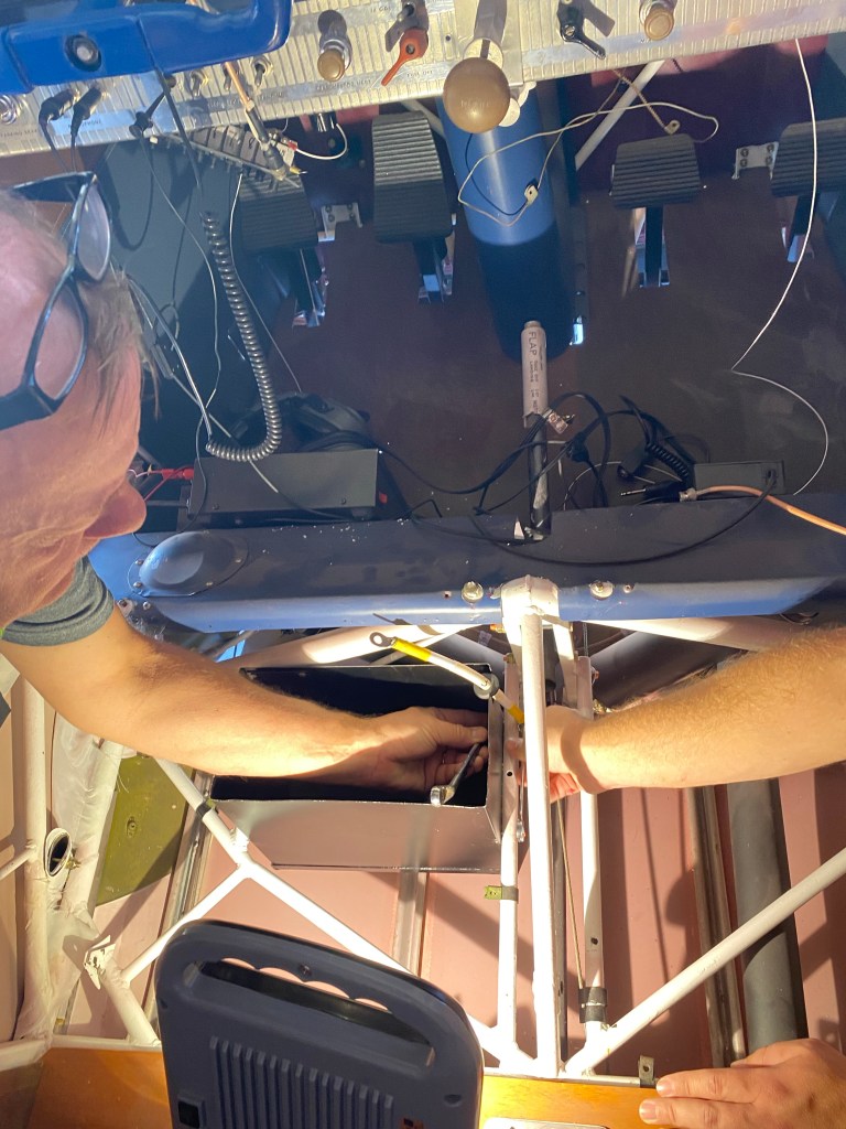
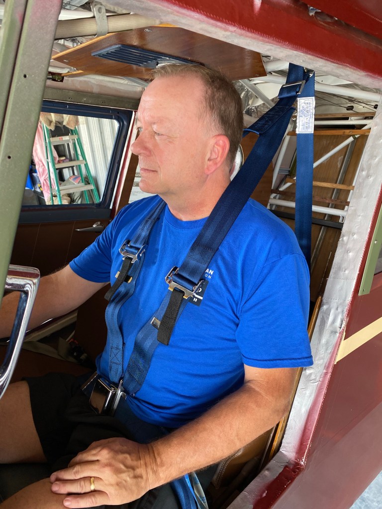
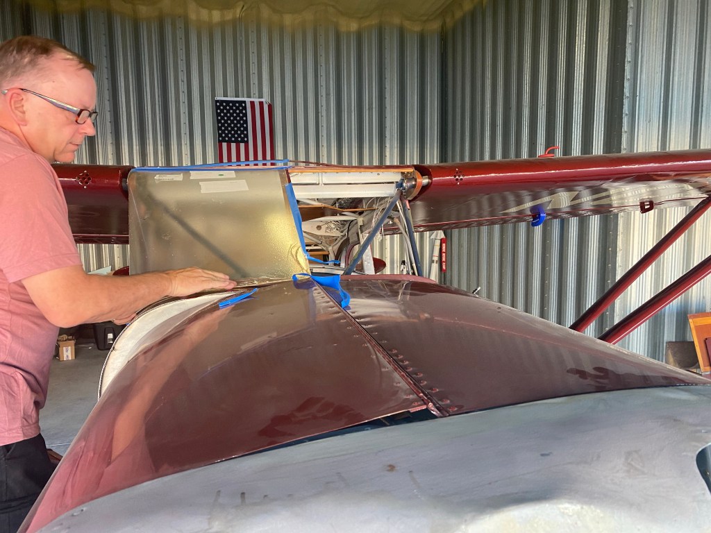
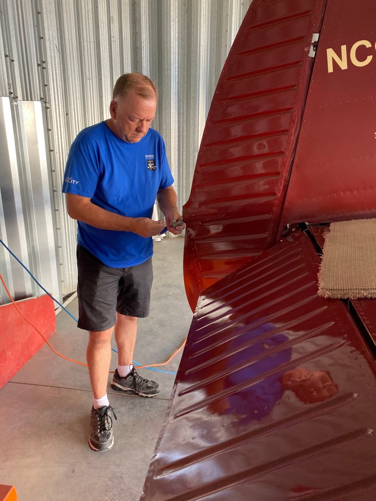
We had some extra help at the hangar today. Aaron came with us after meeting him for lunch.

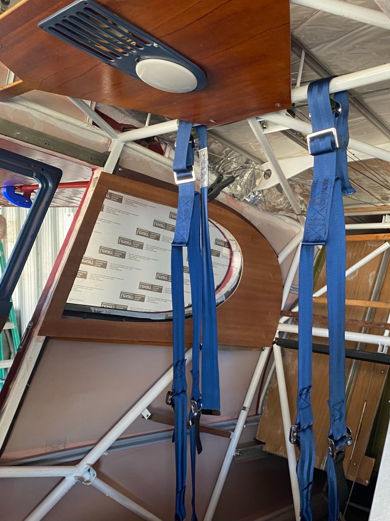
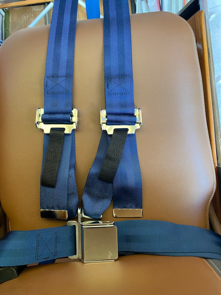
Seat belts and harnesses arrived. Fitting those.
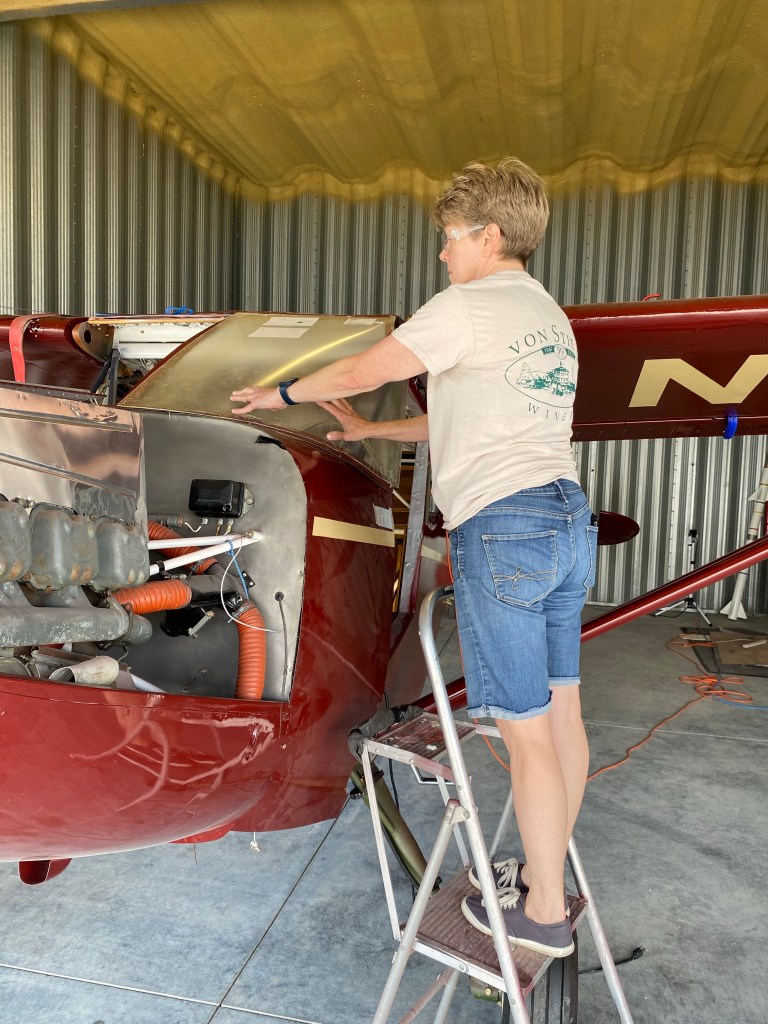
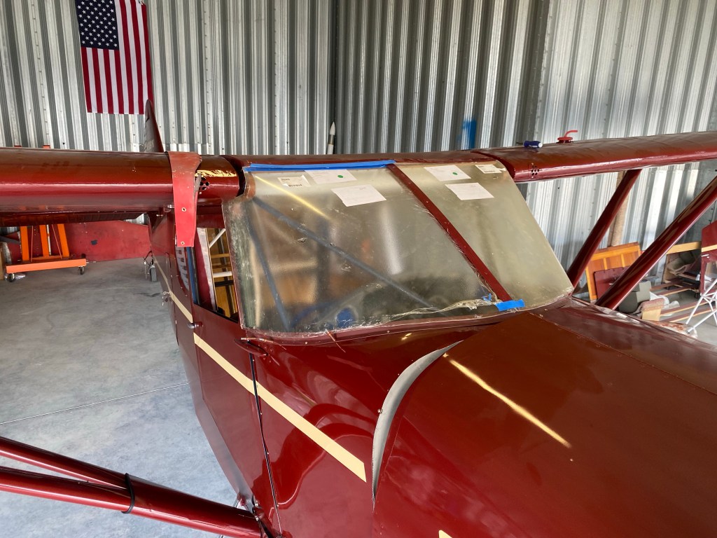
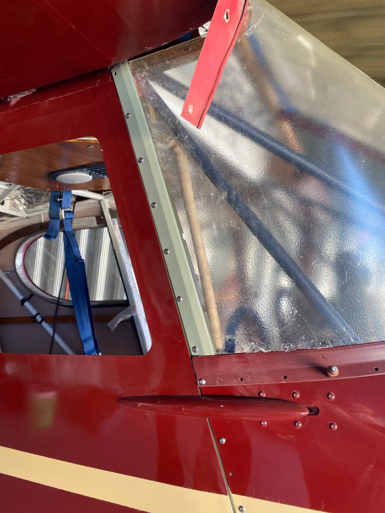
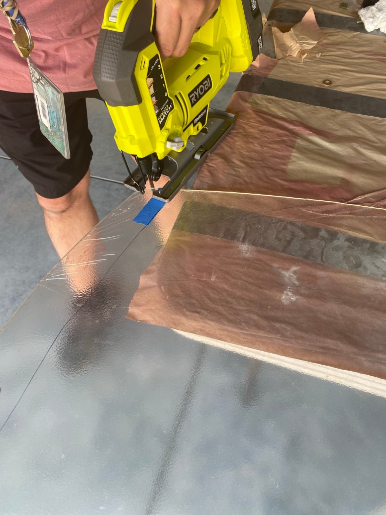
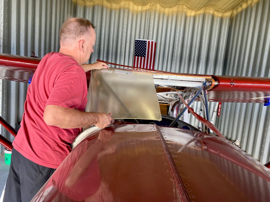
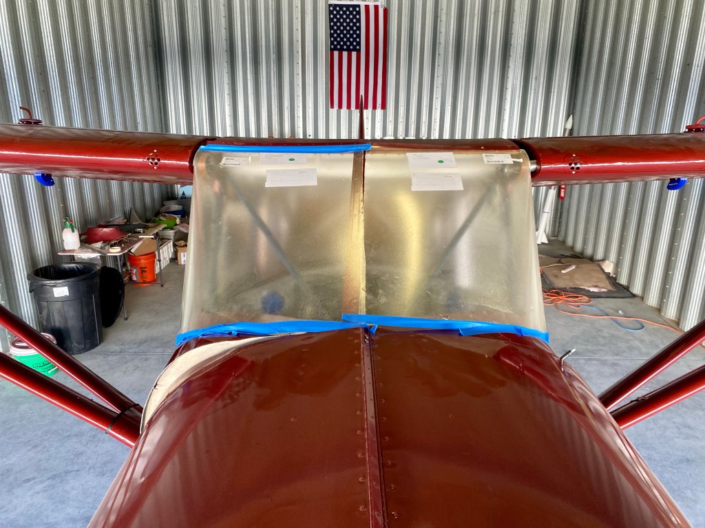
What a nice evening to work at the hangar. Fitting and cutting the right windshield. Taking it slowly to make sure I don’t over cut.

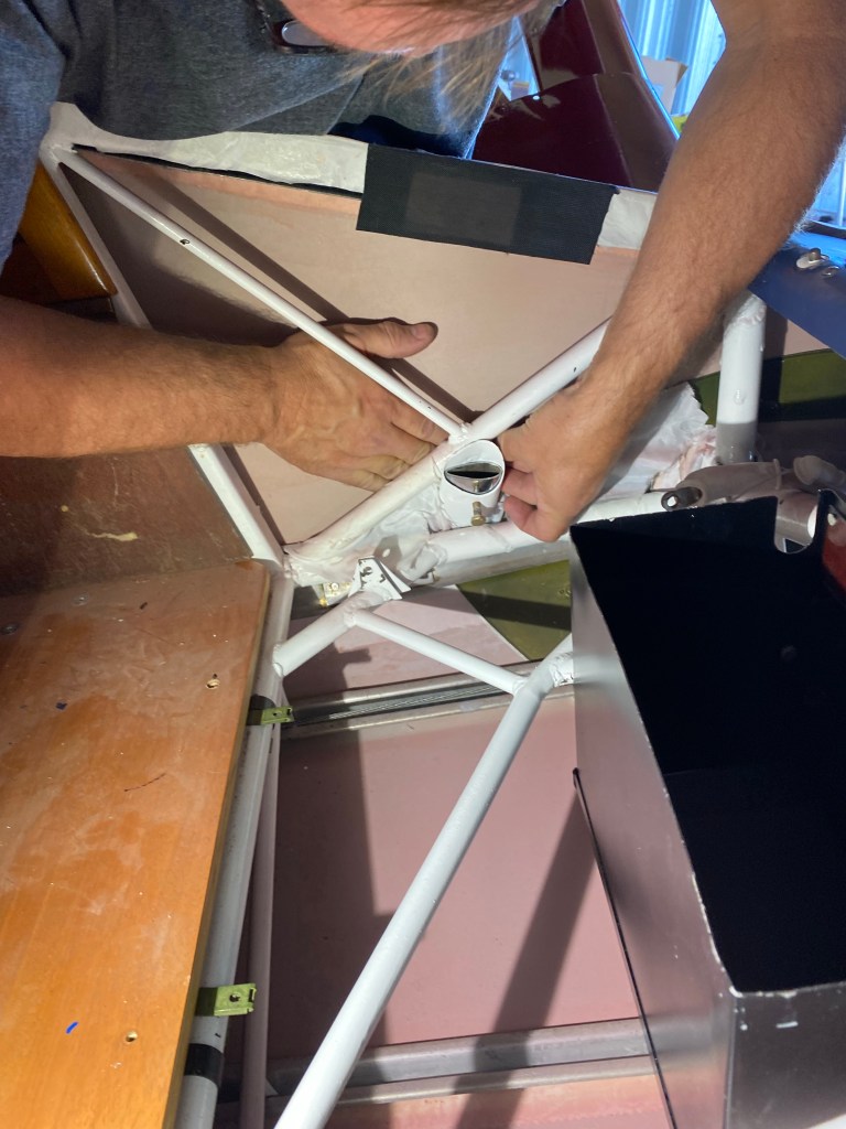
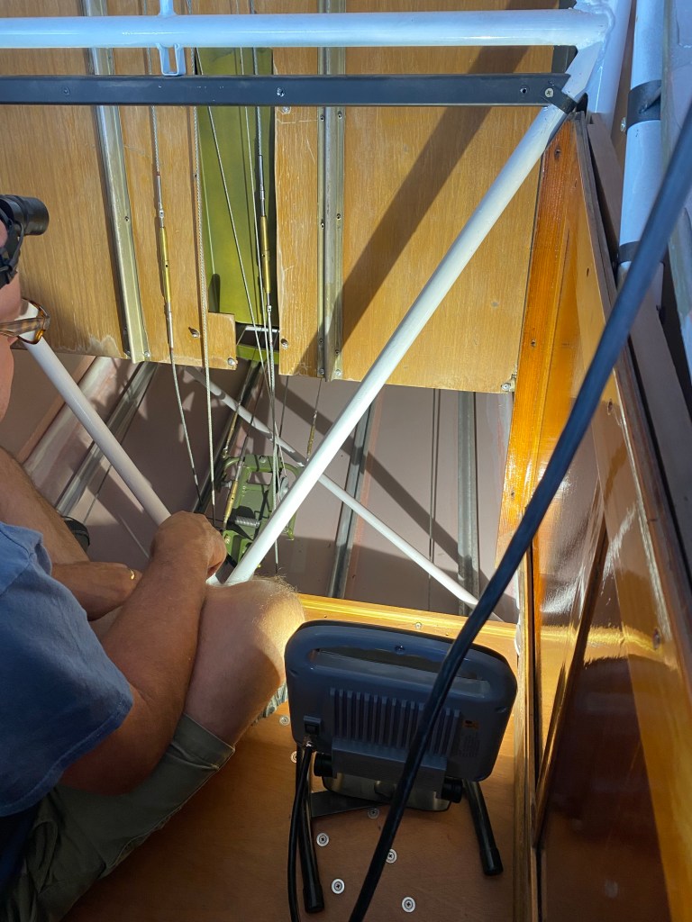
The cables are not tensioned yet, but connected.
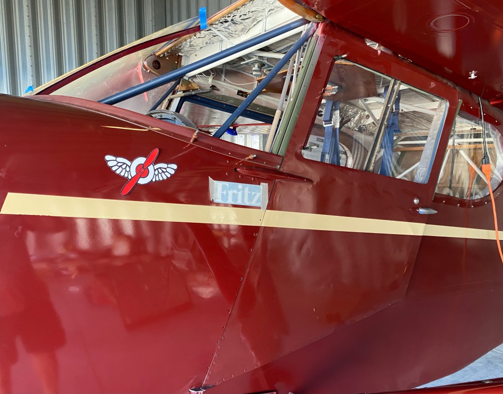
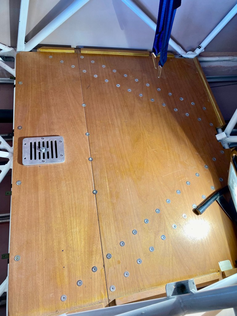
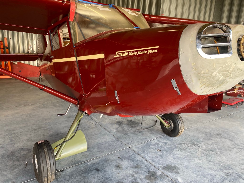
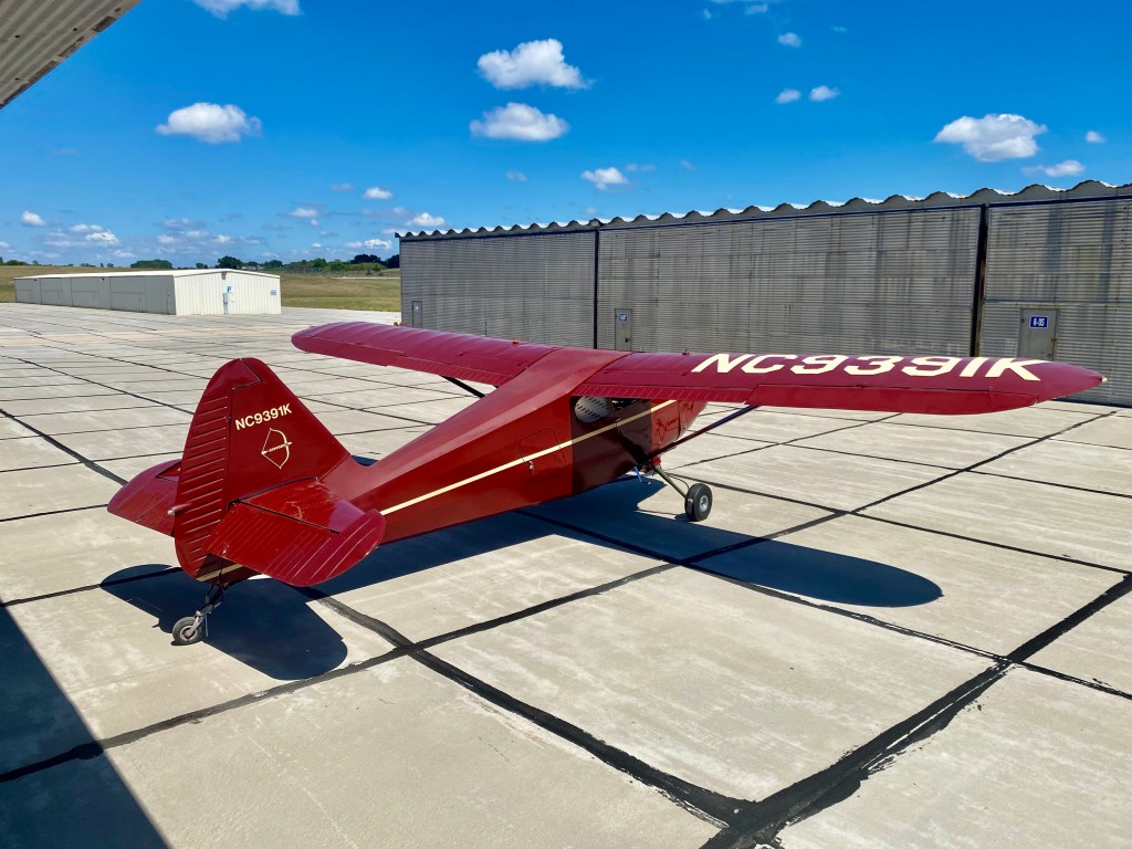
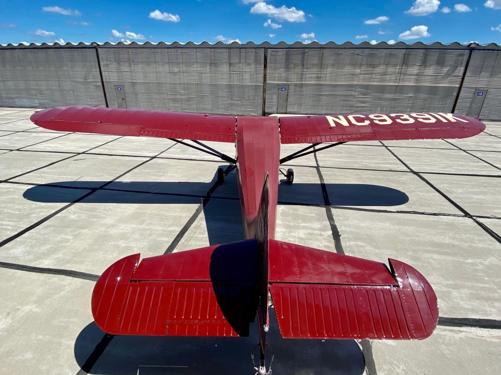
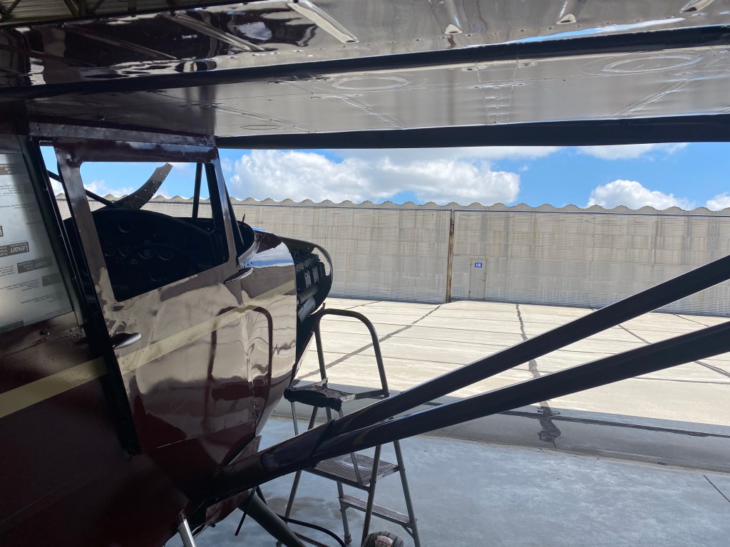
We pushed the Stinson out to clean the hangar floor. Took advantage of it by taking some photos. I should have dusted and polished it first.
Started the process of fitting the windshield.


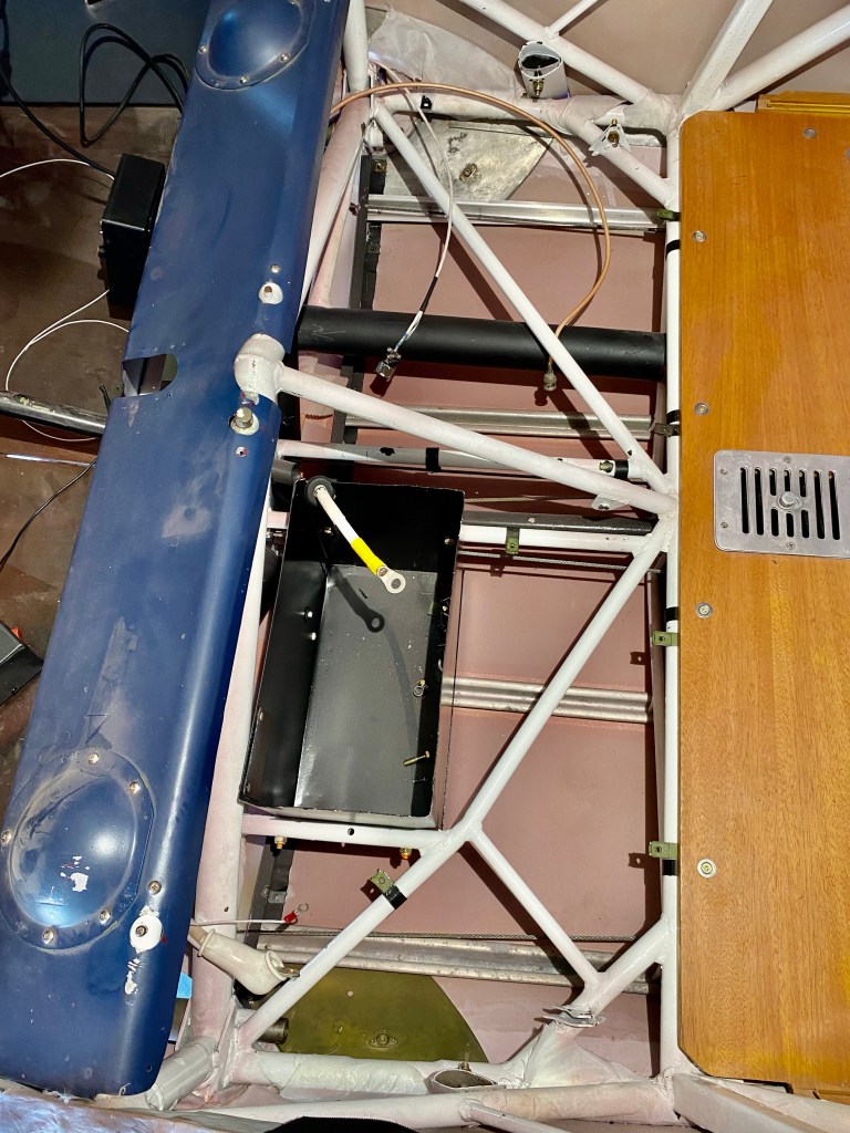
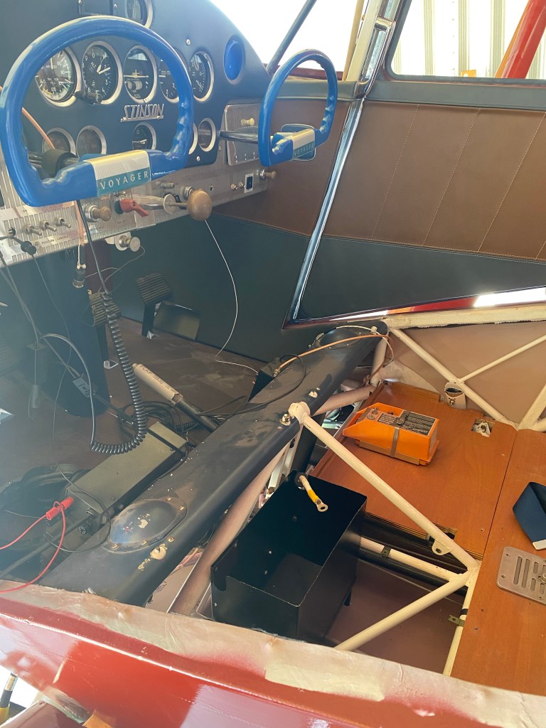
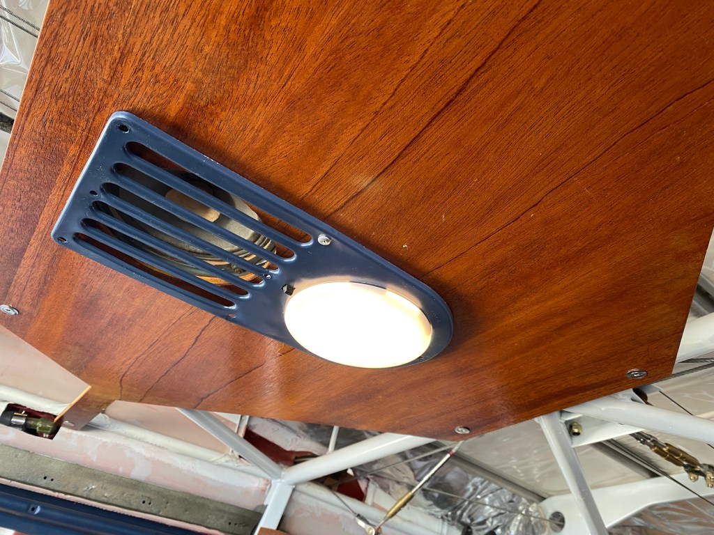
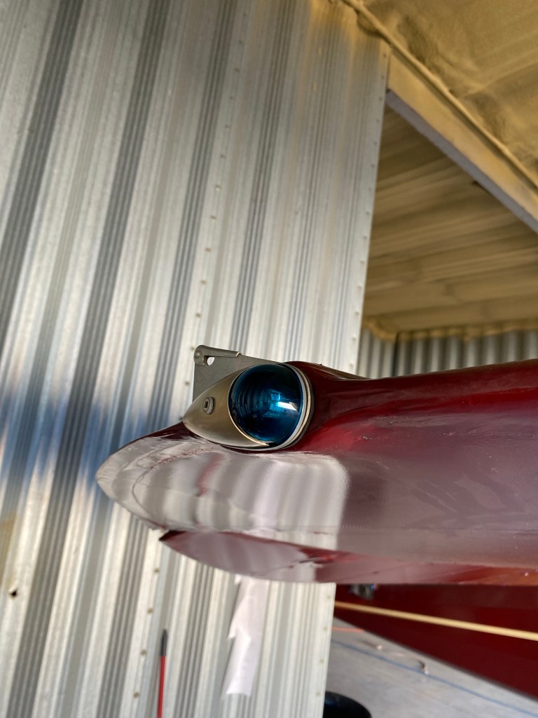
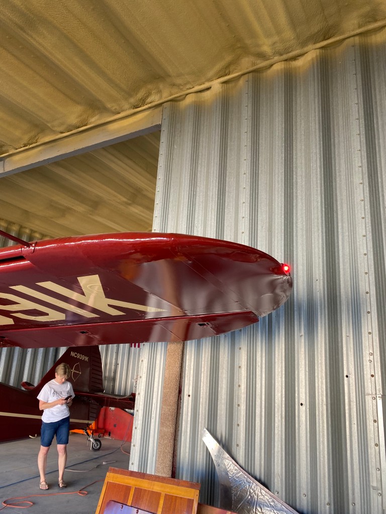
Hooked up the starboard wing tank fuel lines, installed a tail strobe light, installed the mixture and carb heat control cables, connected the cabin light, and adjusted the aileron cables.
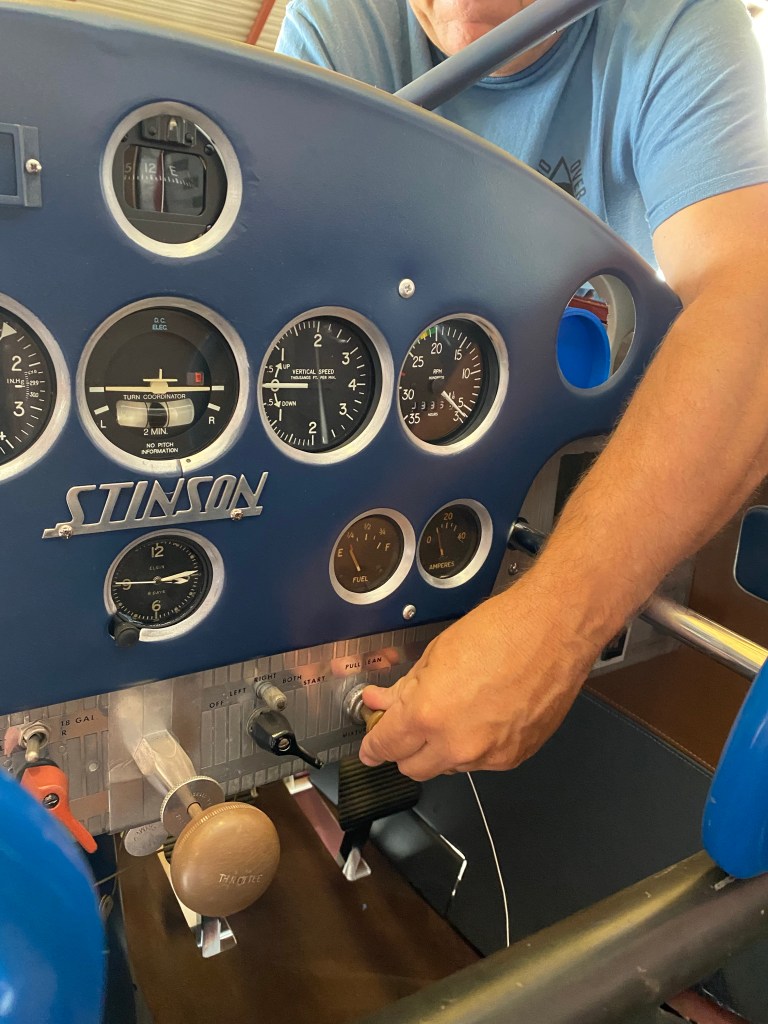
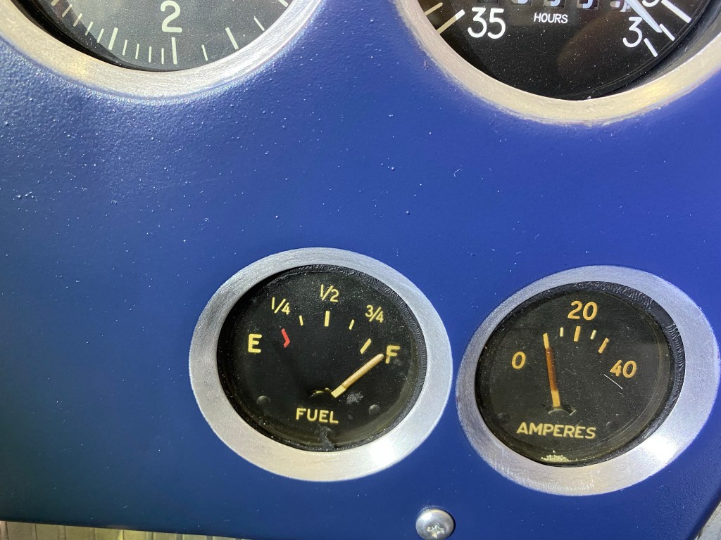
The new LED lights draw a LOT less Amps than the incandescent bulbs.
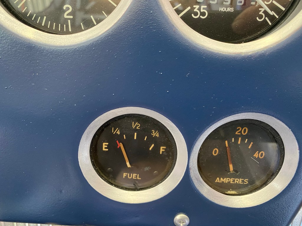
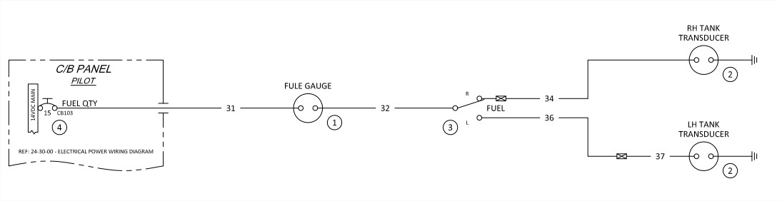
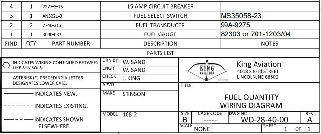
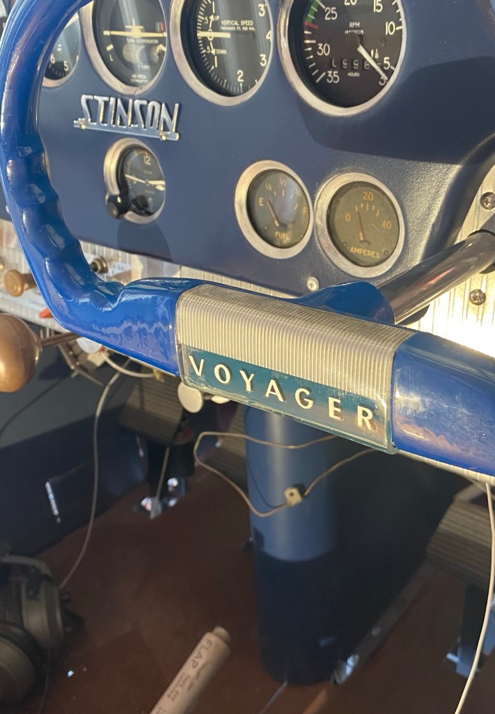
It’s a simple, decades old system that works well. When it works. Some say it’s from General Motors, but the sending unit is a Ford unit. I’m told it’s from a 1938 Ford truck and you can buy the sending unit off a Ford Restoration website for around $43.00 (Part #: 99A-9275).
The Stinson fuel sending unit mounts on the bottom of the fuel tank while the Ford sending unit mounts on the top of the tank. So full fuel in the Ford means low resistance from the sending unit .
In the Stinson, it’s opposite due the sending being mounted upside down. Low or a short indicates empty and high resistance indicates fuel fuel.
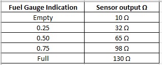
The Ford sending unit linked above shows 125-135 Empty, 17-19 Full, so turning that unit up-side-down you will have 17-19 Empty and 125-135 Full. Seems about right with this Stinson.
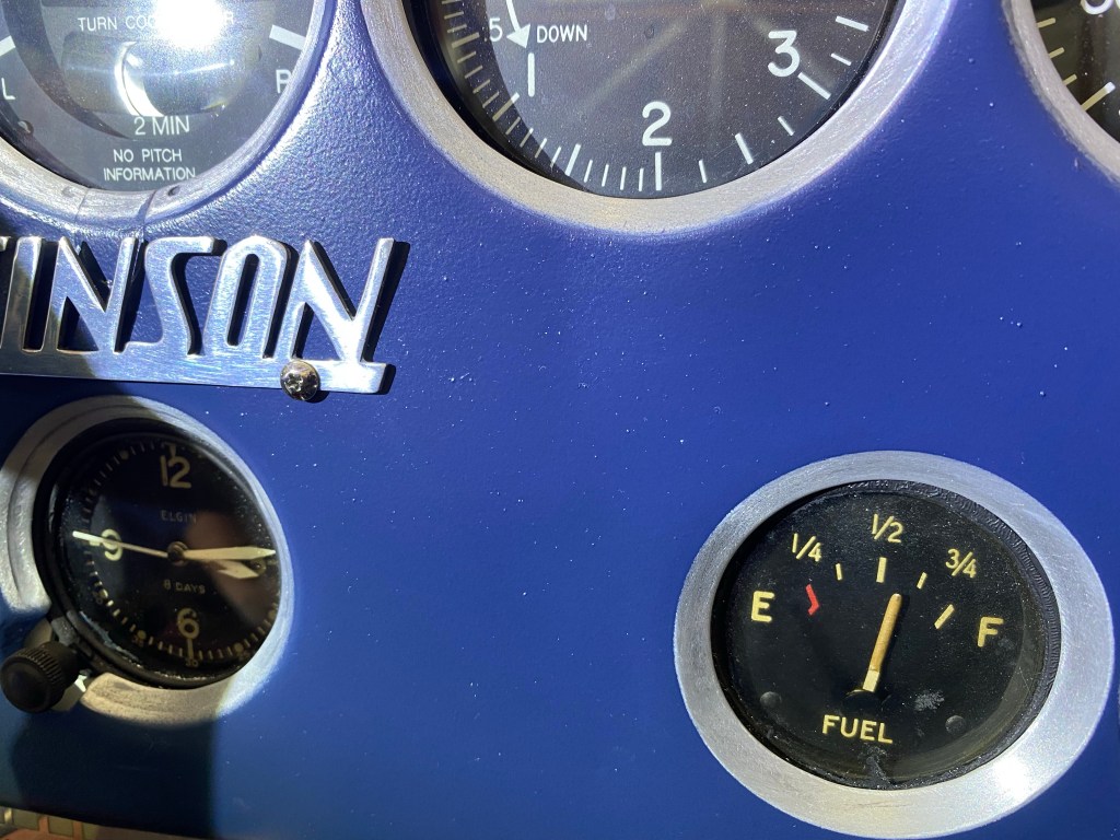
Some Stinson webpages show it wrong, but Larry Wheelock’s post is correct. At least for this Stinson , this is how it works.
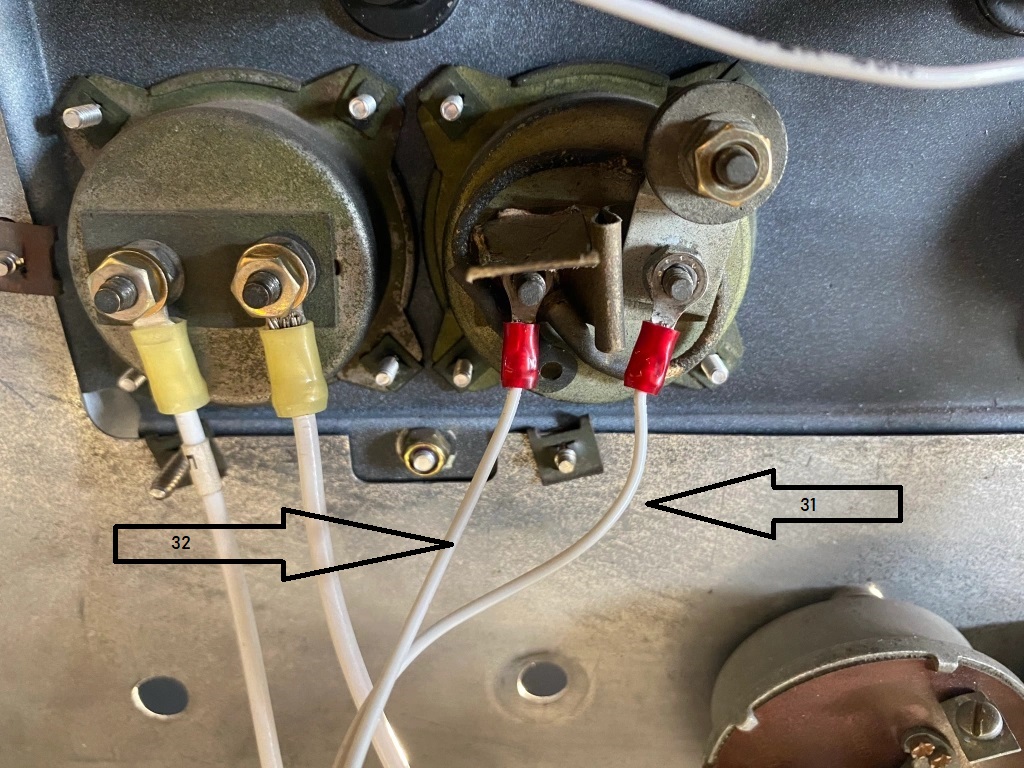
The gauge has three posts. Two are on the right side of the gauge as you view from the rear of the gauge and one post on the left. I’ve read that one post is for 6v systems and one for 12v systems. I connected it to the bottom post for 12v.