Updated 12/1/2020: Watch the 3D printed flap bracket installation video I made here: https://youtu.be/4v0zpSS4QO8
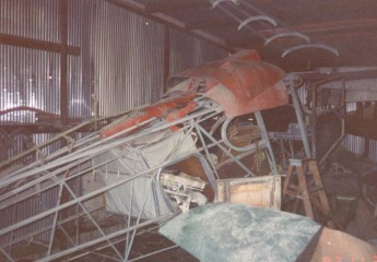
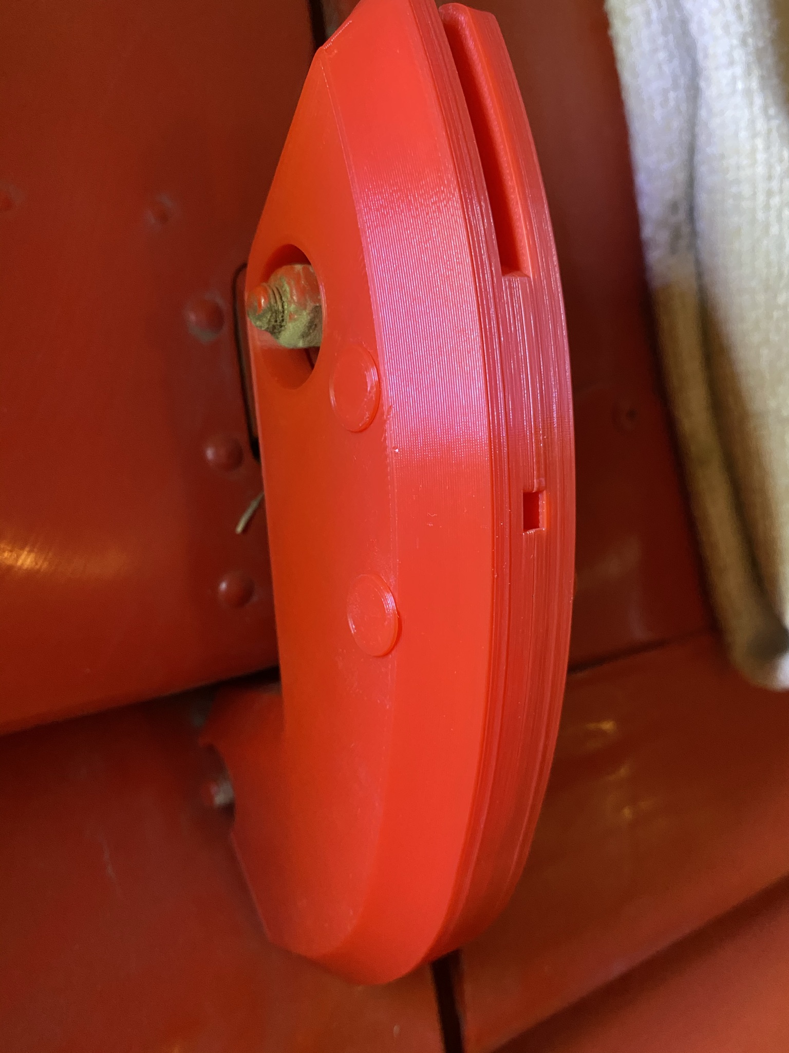
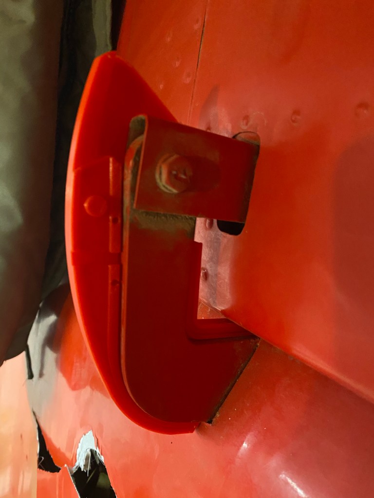
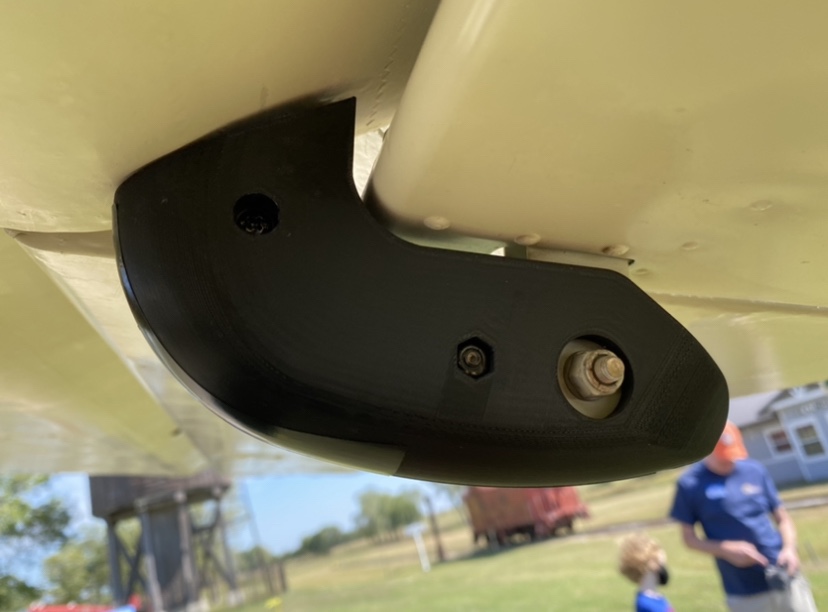
These are hard to find so I designed and printed a few. They came out pretty nice I think. Plastic is ABS so they’ll withstand the temps and I printed a set in flex filament. They came out nice. They are there to keep you from scalping yourself when you walk under the wing.
I understand the factory put these on the 108-3 models only. I’m not sure if that’s accurate as one guy I spoke with has them on his 108-1.
Now I’m making a mold so I can make them out of rubber. I’m using a rubber with a hardness or shore value of 80A. Hard, but flexible. It should prevent scalping yourself. Is there a market for these?
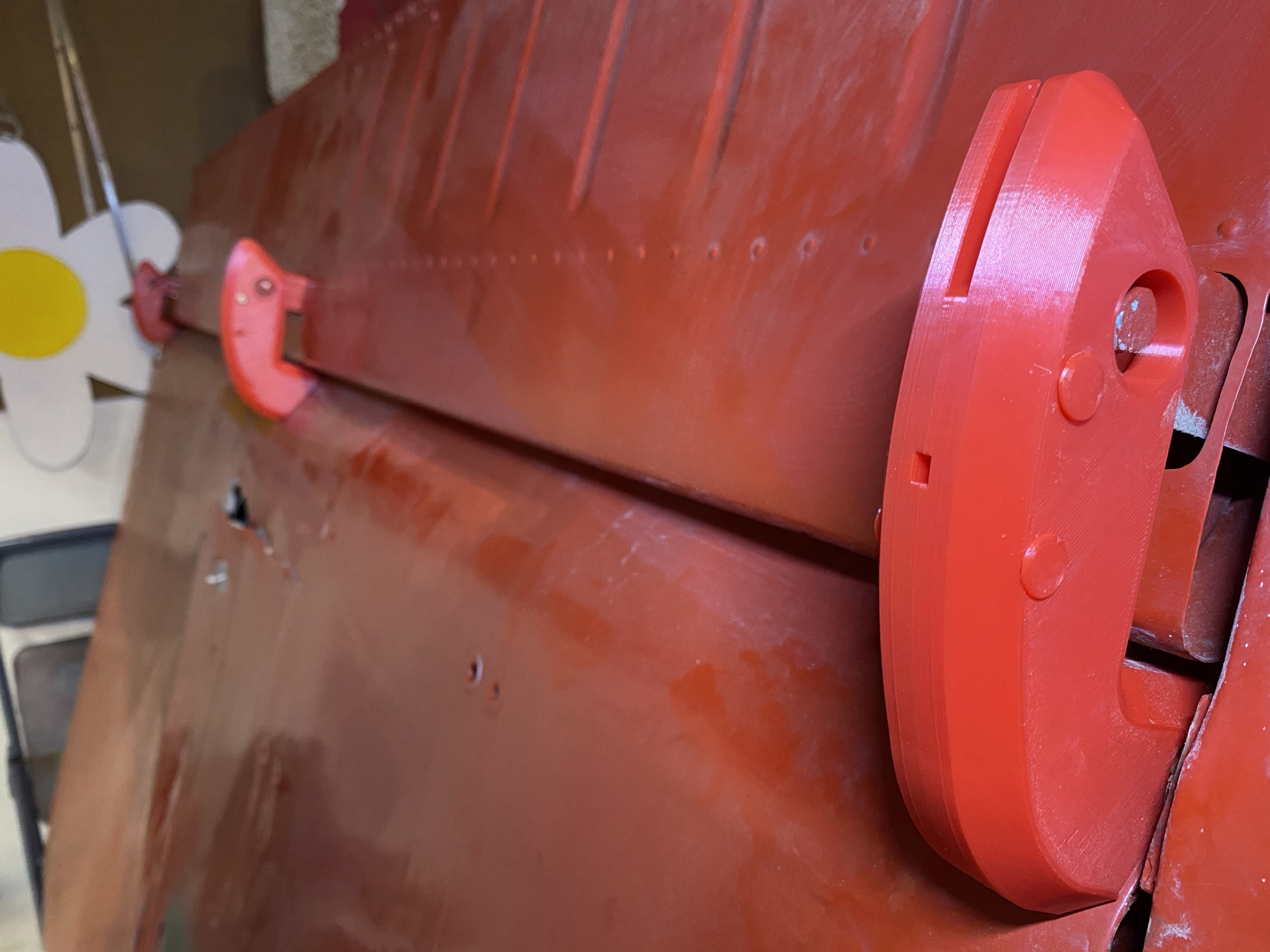
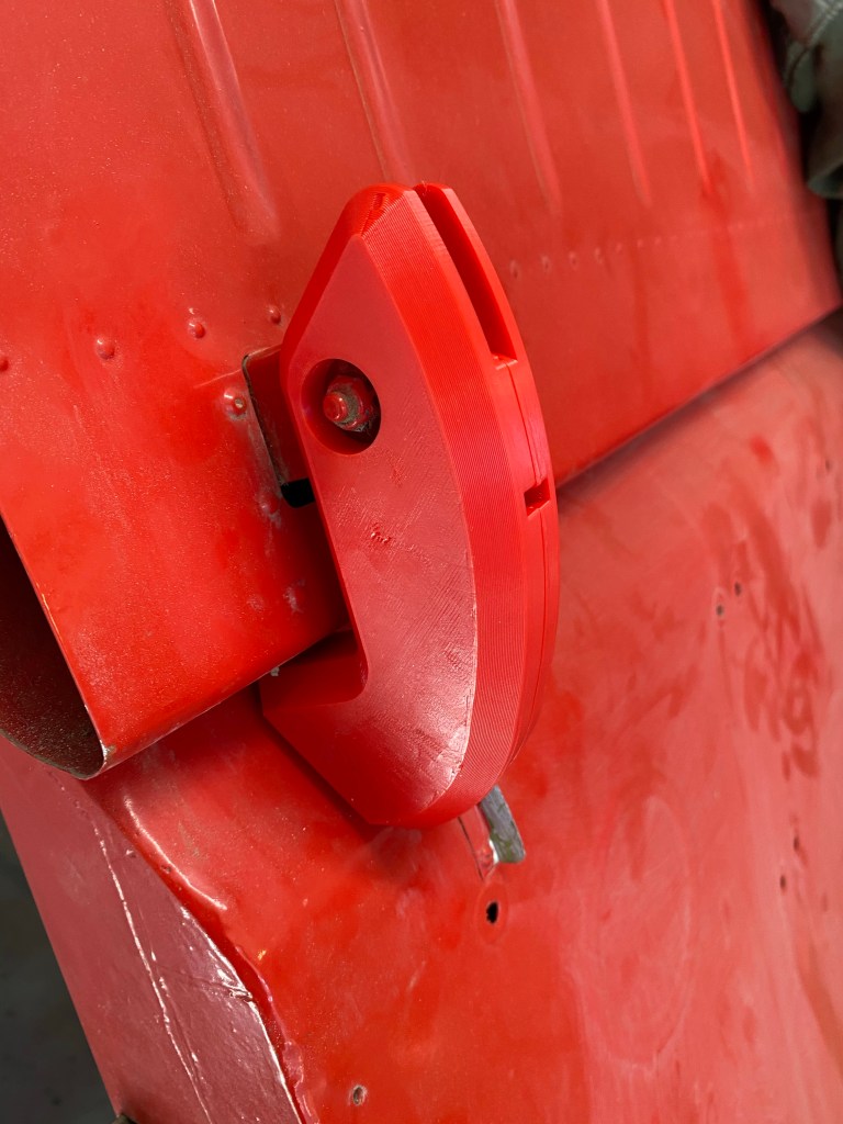
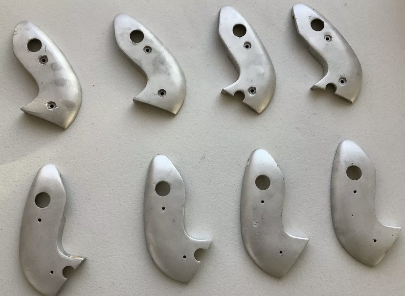
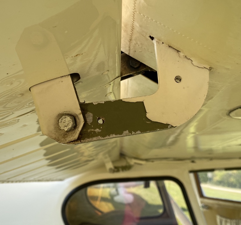
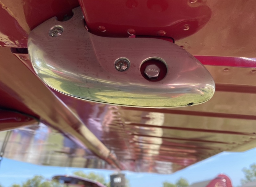
Screw and nut hole covers installed. These are printed in draft mode so the quality is not perfect.All three hinges installed. The first one has the screw holes installed.The two halves snap together here, but I’m currently printing a set that use screws to secure the halves together without drilling any holes in the flap hinge. The outermost flap hinge requires an additional opening for the end bolt. That rectangle hole is there for water to escape. The end is open for inspecting the flap attach point. These are printed in draft mode so the quality isn’t professional at this point. Two holes for screws to keep the two halves together. What the originals look like. Flap hinge with holes for mounting. Mine do not have the holes. Looks like polished aluminum to me. They look like originals. Someone’s Stinson with 3D printed hinges. Notice the mounting holes. It looks like they printed them with FLEX filament.
Update 12-01-2020: Lucas from Univair called me back. He’s been very helpful, but can’t give me a good answer on how to set the drag wire tensions. He gave me a name of an engineer at Univair (Mike Wotovitch) who I haven’t called yet, but Lucas talked to him and said I could call to discuss it with him. Apparently, everyone who would have known is either retired or worse yet, no longer with us.
Update 11-30-2020: I spoke with Lucas at Univair and he thinks the right wing drawing (-1111001-1DWG, at $154.54!) they have contains the info for the drag/anti-drag wires. I also spoke with Gary Redden and he doesn’t think so. Lucas is going to open the drawing when he gets a moment and check it for me.
To mark the measuring points, I drew a line straight up from the centerline of the compression tube to the front and rear spar with a square, then marked the point midway on the spar and made a T. The spar measured 1 1/2” so I placed the mark at 3/4”. I did this on each section of the wing. The wing root bay was hard to do because of the drag wire attachment point being behind some brackets.
Then, using my trammel device, I measured each bay from those points. One Piper owner said to start the measurement from the wing attach point using a bolt for the first measurement.
I read a post on the Short Wing Piper Club about checking the drag wires and it matches with what I’m doing, pulling the wire 1/2″ at the center of the bay and reading the tension. – jlk
Wow. Not much information out there on this subject. I had a wing drag wire that was loose and I tightened it up. Now I need to make sure the wing is straight and the drag wires have the correct tension. The maintenance manual only provides the drag wire tensions, but not how to set them.
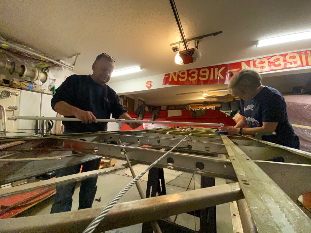
My helper assisting me in checking wing trammel. This bay was right on. Actually, all were right on. And yes, that’s a homemade trammel.
Checking trammel.
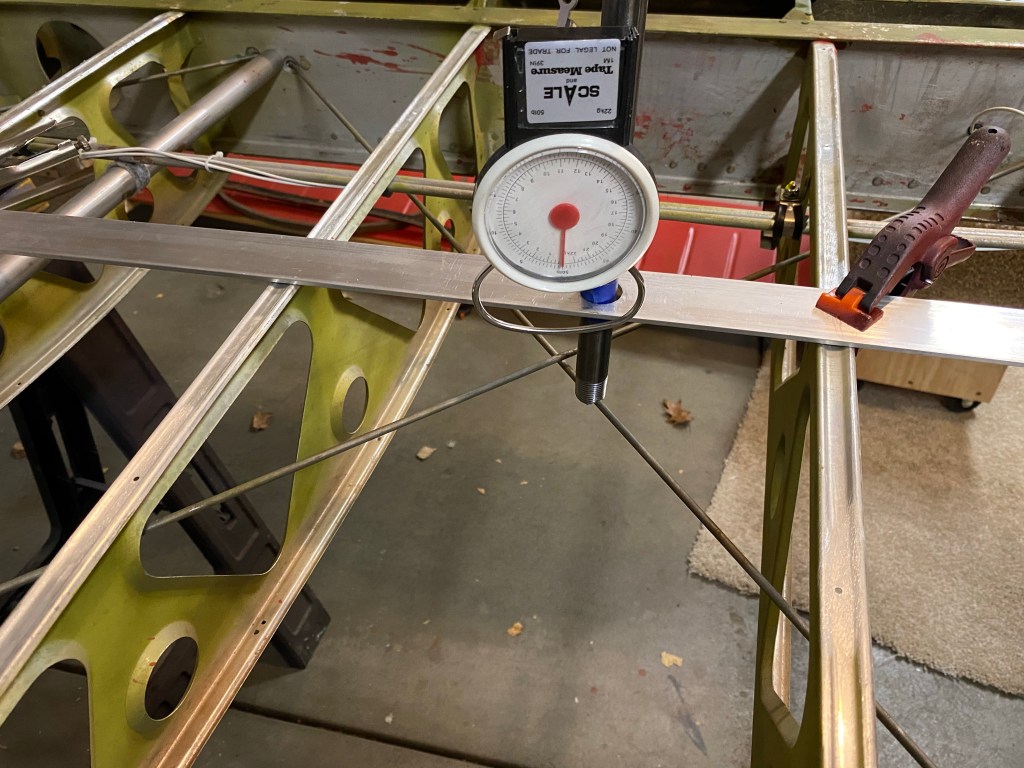
Now, the wing drag tension is a bit tricky. Again, nothing in the manual on this except the tension values. Nothing on how to check them. I watched a video by two gentlemen ( https://www.youtube.com/watch?v=X2fU-1TQg-g )checking the drag wires on a cub and this was their setup. Not sure if the 1/2” pull distance is the same for the Stinson wing. The Stinson service manual provides the tension settings for each bay, but that’s it. I guess this was common knowledge back in the 40’s, but it isn’t now.
The bay I’m testing in the photo is the third bay in from the wing root. The book says 82 lbs of tension, so about 7 ft/lbs of pull. I’m getting 10 ft/lbs on both wires. I’m guessing that if both wires have an even pull and it’s close, it’s good. Any comments?
With this setup, pulling down on the fish scale applies force to the drag wire and the fish scale provides ft/lbs. The Stinson service manual gives in/lbs numbers, so just have to convert it to ft/lbs.